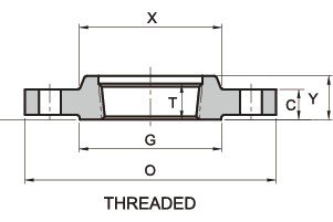
ASME/ANSI B16.5 600 Class Threaded Flange/Standards, Dimensions & Weight
Threaded Flanges, also known as Screwed flanges, have a similar outline to slip-on flanges, but with a threaded bore that allows for assembly without welding. However, this limits their use to relatively low-pressure piping systems. While Threaded Flanges can be welded around the joint after assembly, this method is not recommended for increasing their pressure applications. Typically, Threaded Flanges are used in low-pressure conditions.
- Our company is a manufacturer of ASME/ANSI B16.5 600LB Theaded Flange, which is precisely engineered in accordance with international quality standards. For detailed dimensions of 600 Class Threaded flange, kindly check the table below. Also, you can download the datasheet.

| Product | Threaded Flange |
|---|---|
| Pressure Rating | 600 lb, 600 Class |
| Dimensional Specification | ASME/ANSI B16.5 |
| Size | 1/2″ to 24″ |
| Surface Treatment | Anti-rust Oil, Paint, Zinc, Hot Dipped Galvanized |
| Grades | 304, 304L, 316L, 321, 347, 904L, Duplex, Carbon Steel, Nickel Alloys |
| Test Certificates | As per EN 10204 3.1 |
| Inspection | Videos, Pictures, Inspection Report with Goods |
| Pipe Normal Diam. | O.D. Flange | Thk. Of Flange Min | Diam. of Hub |
Diameter of Raised Face | Length Hub | Thread Length | Diam. of Bolt Circle |
Diam. of Bolt Holes |
Number of Bolts |
Diam. of Bolts (inch) |
Approx. Weight | ||
| inch | dn | O | C | X | G | Y | T | BC | BH | BN | BD | KG/PCS | LB/PCS |
| 1/2″ | 15 | 95.5 | 14.2 | 38.1 | 35.1 | 22.4 | 22.4 | 66.5 | 15.7 | 4 | 1/2″ | 0.9 | 2 |
| 3/4″ | 20 | 117. 5 | 15.7 | 47.8 | 42.9 | 25.4 | 27.7 | 82.6 | 19.1 | 4 | 5/8″ | 1.4 | 3.1 |
| 1″ | 25 | 124. 0 | 17.5 | 53.8 | 50.8 | 26.9 | 34.5 | 88.9 | 19.1 | 4 | 5/8″ | 1.8 | 4 |
| 1-1/4″ | 32 | 133. 5 | 20.6 | 63.5 | 63.5 | 28.4 | 43.2 | 98.6 | 19.1 | 4 | 5/8″ | 2.3 | 5 |
| 1-1/2″ | 40 | 155. 5 | 22.4 | 69.9 | 73.2 | 31.8 | 49.5 | 114.3 | 22.4 | 4 | 3/4″ | 3.3 | 7.3 |
| 2″ | 50 | 165. 0 | 25.4 | 84.1 | 91.9 | 36.6 | 62 | 127 | 19.1 | 8 | 5/8″ | 4 | 8.8 |
| 2-1/2″ | 65 | 190. 5 | 28.4 | 100.1 | 104.6 | 41.1 | 74.7 | 149.4 | 22.4 | 8 | 3/4″ | 5.5 | 12.1 |
| 3″ | 80 | 209. 5 | 31.8 | 117.3 | 127 | 46 | 90.7 | 168.1 | 22.4 | 8 | 3/4″ | 7.4 | 16.3 |
| 3-1/2″ | 90 | 228. 5 | 35.1 | 133.4 | 139.7 | 49.3 | 103.4 | 184.2 | 25.4 | 8 | 7/8″ | 9.2 | 20.2 |
| 4″ | 100 | 273. 0 | 38.1 | 152.4 | 157.2 | 53.8 | 116.1 | 215.9 | 25.4 | 8 | 7/8″ | 16.8 | 37 |
| 5″ | 125 | 330. 0 | 44.5 | 189 | 185.7 | 60.5 | 143.8 | 266.7 | 28.4 | 8 | 1″ | 28.5 | 62.8 |
| 6″ | 150 | 355. 5 | 47.8 | 222.3 | 215.9 | 66.5 | 170.7 | 292.1 | 28.4 | 12 | 1″ | 36.2 | 79.8 |
| 8″ | 200 | 419. 0 | 55.6 | 273.1 | 269.7 | 76.2 | 221.5 | 349.3 | 31.8 | 12 | 1 1/8″ | 21.5 | 114 |
| 10″ | 250 | 508. 0 | 63.5 | 342.9 | 323.9 | 85.9 | 276.4 | 431.8 | 35.1 | 16 | 1 1/4″ | 76.2 | 168 |
| 12″ | 300 | 559. 0 | 66.5 | 400.1 | 381 | 91.9 | 327.2 | 489 | 35.1 | 20 | 1 1/4″ | 89.5 | 197 |
| 14″ | 350 | 603. 5 | 69.9 | 431.8 | 412.8 | 93.7 | 359.2 | 527.1 | 38.1 | 20 | 1 3/8″ | 102 | 225 |
| 16″ | 400 | 686. 0 | 76.2 | 495.3 | 469.9 | 106. 4 | 410.5 | 603.3 | 41.1 | 20 | 1 1/2″ | 150 | 330 |
| 18″ | 450 | 743. 0 | 82.6 | 546.1 | 533.4 | 117. 3 | 461.8 | 654.1 | 44.5 | 20 | 1 5/8″ | 180 | 397 |
| 20″ | 500 | 813. 0 | 88.9 | 609.6 | 584.2 | 127. 0 | 513.1 | 723.9 | 44.5 | 24 | 1 5/8″ | 231 | 509 |
| 24″ | 600 | 940. 0 | 101.6 | 717.6 | 692.2 | 139. 7 | 616 | 838.2 | 50.8 | 24 | 1 7/8″ | 330 | 727 |
