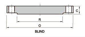
ASME/ANSI B16.47 Series B-API 300 Class Blind Flange/Standards, Dimensions & Weight
Blind Flange is flanges that designed to be joined to a piping system by butt welding. This kind of flange include lots of specification, weld neck flange is expensive because of its long neck and cost of people for contact Blind flange with pipeline or fitting, but is preferred for high stress applications. The necks, or hubs, transmits stresses to the pipeline. The gradual transition of thickness from the base of the hub to the wall thickness at the butt weld provides important reinforcement of the blind flange. The bore of Blind flange matches bore of the pipeline, reducing turbulence and erosion.
- Our company is a manufacturer of ASME/ANSI B16.47 Series B-API Blind Flange, which is precisely engineered in accordance with international quality standards. For detailed dimensions of 300 Class Blind flange, kindly check the table below. Also, you can download the datasheet.

| Product | Blind Flange |
|---|---|
| Pressure Rating | 300 lb, 300 Class |
| Dimensional Specification | ASME/ANSI B16.5 |
| Size | 26″ to 60″ |
| Surface Treatment | Anti-rust Oil, Paint, Zinc, Hot Dipped Galvanized |
| Grades | 304, 304L, 316L, 321, 347, 904L, Duplex, Carbon Steel, Nickel Alloys |
| Test Certificates | As per EN 10204 3.1 |
| Inspection | Videos, Pictures, Inspection Report with Goods |
| Pipe Normal Diam. | O.D. OF Flange |
Thickness | Raised Face Diam. |
Diam. of Bolt Circle |
No. of Bolt Holes |
Diam. of Bolt Holes |
Diam. of Bolt |
Fillet Radius Min. |
| inch | O | C | R | BD | BN | BH | DB | r1 |
| 26″ | 866.6 | 88.9 | 736.6 | 803.1 | 32 | 35.1 | 1 1/4 | 14.2 |
| 28″ | 920.8 | 88.9 | 787.4 | 857.3 | 36 | 35.1 | 1 1/4 | 14.2 |
| 30″ | 990.6 | 93.7 | 844.6 | 920.8 | 36 | 38.1 | 1 3/8 | 14.2 |
| 32″ | 1054.1 | 103.1 | 901.7 | 977.9 | 32 | 41.1 | 1 1/2 | 15.7 |
| 34″ | 1107.9 | 103.1 | 952.5 | 1031.7 | 36 | 41.1 | 1 1/2 | 15.7 |
| 36″ | 1171.4 | 103.1 | 1009.7 | 1089.2 | 32 | 44.5 | 1 5/8 | 15.7 |
| 38″ | 1222.2 | 111.3 | 1060.5 | 1140 | 36 | 44.5 | 1 5/8 | 15.7 |
| 40″ | 1273 | 115.8 | 1114.6 | 1190.8 | 40 | 44.5 | 1 5/8 | 15.7 |
| 42″ | 1333.5 | 119.1 | 1168.4 | 1244.6 | 36 | 47.8 | 1 3/4 | 15.7 |
| 44″ | 1384.3 | 127 | 1219.2 | 1295.4 | 40 | 47.8 | 1 3/4 | 15.7 |
| 46″ | 1460.5 | 130 | 1270 | 1365.3 | 36 | 50.8 | 1 7/8 | 15.7 |
| 48″ | 1511.3 | 134.9 | 1327.2 | 1416.1 | 40 | 50.8 | 1 7/8 | 15.7 |
| 50″ | 1562.1 | 139.7 | 1378 | 1466.9 | 44 | 50.8 | 1 7/8 | 15.7 |
| 52″ | 1612.9 | 144.3 | 1428.8 | 1517.7 | 48 | 50.8 | 1 7/8 | 15.7 |
| 54″ | 1673.4 | 149.4 | 1479.6 | 1577.8 | 48 | 50.8 | 1 7/8 | 15.7 |
| 56″ | 1765.3 | 157 | 1536.7 | 1651 | 36 | 60.5 | 2 1/4 | 17.5 |
| 58″ | 1827.3 | 162.1 | 1593.9 | 1713 | 40 | 60.5 | 2 1/4 | 17.5 |
| 60″ | 1878.1 | 166.6 | 1651 | 1763.8 | 40 | 60.5 | 2 1/4 | 17.5 |
